
A practical guide to image quality, normal anatomy, tooth and supporting-structure assessment, descriptive reporting, and the limits of a two-dimensional image.
A small dental radiograph can contain a surprising amount of information: tooth structure, restorations, roots, periodontal support, anatomical landmarks, developing teeth, and possible disease. The challenge is not simply recognising a dark area. It is deciding what is visible, whether the image is adequate, and how the findings relate to the patient.
Use the same reading sequence every time. Describe the evidence before naming the disease.
This article explains how to read an intraoral periapical radiograph, commonly called an IOPA in Indian dental teaching. You may also see the terms periapical radiograph, PA, or intraoral periapical image. Interpretation principles apply to film, phosphor plates, and solid-state digital receptors, although their acquisition and display characteristics differ.
The clinical images below are credited teaching examples, not complete patient records. The original diagrams are labelled schematics, not simulated diagnostic radiographs.
In this guide:
- What an IOPA should show, and what it cannot show
- Start with the patient, indication, and image identity
- Check image quality before interpreting disease
- Use a repeatable reading sequence
- Learn the normal appearance first
- Know the landmarks that commonly mimic disease
- Examine the crown and restorations
- Follow the pulp space and every visible root
- Assess periodontal support systematically
- Assess the periapical region without jumping to “abscess”
- Describe an abnormality before interpreting it
- Three clinical image exercises
- Two fictional interpretation problems
- Write a concise report
- When is another view or modality useful?
- Twenty viva questions with explained answers
What an IOPA should show, and what it cannot show
A periapical view is intended to include the tooth or teeth of interest from crown to root apex, together with surrounding bone. A commonly taught coverage criterion is approximately 2-3 mm of bone beyond the apex, provided the full region requiring investigation is included. A lesion extending farther requires coverage appropriate to that lesion.
An IOPA is a projection of three-dimensional structures onto a two-dimensional receptor. Buccal and lingual structures can overlap. Root number, canal number, lesion extent, and the relationship between a root and an anatomical space may therefore be uncertain.
A dark area superimposed on an apex is not necessarily centred on that apex in three dimensions. Similarly, a root apparently crossing the maxillary sinus floor on one projection has not thereby been proved to protrude into the sinus.
An IOPA is an aid to diagnosis. It cannot independently establish the pulp’s blood supply, identify every crack, determine the histological lining of a lesion, or provide a full periodontal examination.
Start with the patient, indication, and image identity
Before inspecting the tooth, establish whose image it is and why it was taken.
Check the patient identifier in the clinical record, acquisition date, anatomical region, side, and available previous images. Confirm the clinical question: pain localisation, trauma, root morphology, periapical assessment, treatment review, or another indication.
The same image may answer one question adequately and another poorly. A view that records the apices may still have overlapping contacts that limit proximal-caries assessment.
Do not prescribe an image simply because a patient is new or because a routine interval has elapsed. Current ADA/AAOMR selection recommendations emphasise clinical history, examination, risk, the specific problem, and review of existing images. These are international references; local practice and regulatory requirements also apply.
Confirm orientation without guessing
In conventional labial mounting, the images are arranged as though the clinician is facing the patient: the patient’s right appears on the viewer’s left. For film, the identification dot and its convexity support correct mounting. Digital images require verification of the recorded orientation and acquisition information.
Morphology and landmarks help confirm the region, but do not invent a side from a cropped, unlabelled image. If orientation is uncertain, state that uncertainty before assigning an FDI tooth number. Rotation changes presentation; horizontal mirroring can reverse right and left.
Check image quality before interpreting disease
Ask one practical question: Does this image contain enough reliable information to answer its clinical question?
| Check | What to inspect | Consequence of a limitation |
|---|---|---|
| Coverage | Crown, roots, apices, adjacent structures, and the area of concern | An excluded region cannot be declared normal |
| Projection geometry | Shape distortion, root overlap, contact overlap, receptor bending | Apparent lengths and relationships may be misleading |
| Sharpness | Motion blur or loss of fine detail | Small structural changes may be unassessable |
| Contrast and useful exposure | Can relevant tissues and boundaries be distinguished? | Very poor exposure or display can obscure information |
| Artifacts | Receptor damage, processing marks, foreign objects, software effects | An apparent lesion or line may not be anatomical |
| Display and comparison | Appropriate viewing conditions and comparable previous images | A change in appearance may reflect technique rather than disease |
Common errors students should recognise
- Cone cut: an unexposed region caused by the beam failing to cover the receptor; it is not a missing piece of jaw.
- Contact overlap: often associated with incorrect horizontal beam alignment, limiting assessment of the affected surfaces.
- Elongation or foreshortening: altered projected tooth shape caused by unsuitable tooth–receptor–beam geometry.
- Missing apices: inadequate coverage for an apical question, potentially related to receptor placement and projection.
- Motion or damaged receptors: reduced detail or misleading marks.
The corrective action depends on the actual error and technique. Avoid applying one memorised angulation adjustment to every geometry problem.
A digital image’s brightness is not a dependable exposure meter: processing can change its appearance. Adjusting the display may help review existing information, but it cannot restore an excluded apex or recover detail that was never recorded. Never repeat an exposure merely to make an already adequate teaching image prettier; assess whether the missing information is clinically necessary.
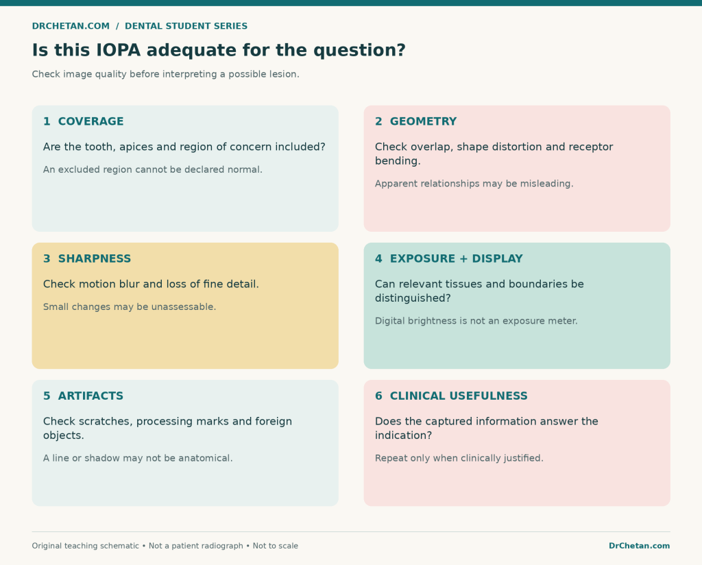
Figure 1. Evaluate adequacy for the specific question. These are quality checks, not instructions for a universal exposure setting.
Use a repeatable reading sequence
One useful sequence is:
- Identity and quality: verify the patient, region, orientation, indication, and limitations.
- Overall survey: look across the entire image before concentrating on one tooth.
- Crowns and restorations: assess tooth structure, contacts, visible defects, and restorative materials.
- Pulp spaces and roots: inspect chambers, canals, root form, and visible treatment.
- Periodontal support: trace the periodontal ligament space, lamina dura, crests, and furcations.
- Periapical region: evaluate the surrounding bone and any change associated with a root end.
- Other anatomy and findings: review landmarks, adjacent teeth, borders, and the image edges.
- Description and conclusion: document findings, uncertainties, clinical correlation, and any justified next assessment.
The order is a learning aid, not a named universal standard. Its value is consistency. Finding an obvious cavity at step three should not stop the remaining review.
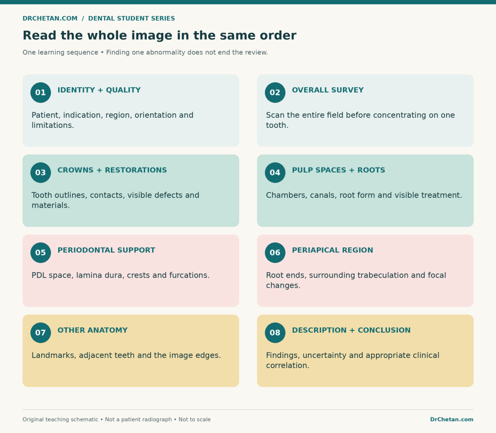
Figure 2. Repeat the whole sequence. Looking only at the symptomatic tooth can miss unrelated findings.
Learn the normal appearance first
Radiolucent and radiopaque are descriptive terms
On the usual non-inverted display, relatively radiolucent areas appear darker and relatively radiopaque areas appear lighter. The appearance reflects attenuation along the beam path and the imaging system.
Air spaces, canals, and foramina can be radiolucent. Mineralised structures and many restorative materials can be radiopaque. Neither term means “diseased” or “healthy.” Some lesions are radiolucent, some radiopaque, and others mixed.
Tooth structures
| Structure | Expected appearance | Important limitation |
|---|---|---|
| Enamel | A relatively highly radiopaque outer crown layer | Its projected thickness varies with anatomy and beam direction |
| Dentin | Less radiopaque than enamel, forming most of the tooth | Radiographic appearance does not directly measure hardness or histology |
| Pulp chamber and canals | Relatively radiolucent internal spaces | Their visibility and apparent size vary with development, age, calcification, and projection |
| Cementum | Normally not distinguishable as a separate thin layer from root dentin | Do not confidently label a fine root outline as visible cementum |
| Dentinoenamel junction | The interface between enamel and dentin | Optical contrast and superimposition can affect its appearance |
The radiolucent pulp space is the visible outline of a space containing soft tissue. It is not a photograph of living pulp and cannot establish vitality.
Supporting structures
The periodontal ligament space appears as a relatively radiolucent line around the root. The lamina dura is the relatively radiopaque image of the socket’s compact bony lining. Trace them together, rather than searching for one isolated dark or white line.
Assess continuity, contour, and local changes. Their appearance varies with projection, anatomy, and function; an indistinct portion of lamina dura on one image is not automatically proof of disease.
Inspect the alveolar crest in relation to adjacent cementoenamel junctions, and compare the visible trabecular pattern. Trabeculae are relatively radiopaque; marrow spaces between them are relatively radiolucent. Normal patterns vary by region and patient.
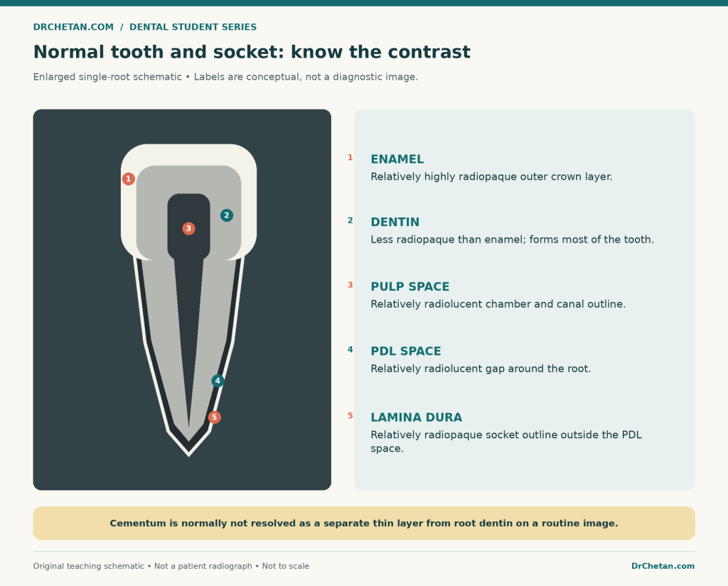
Figure 3. Teaching schematic, not a radiograph. The periodontal space and socket line are enlarged for explanation; cementum is not depicted as a separately identifiable radiographic layer.
Know the landmarks that commonly mimic disease
You do not need to name every landmark before reporting an IOPA. You do need to recognise when a normal structure could explain what you are seeing.
Maxillary anterior region
Look for the nasal cavity, its floor and septum, the anterior nasal spine, and the incisive or nasopalatine foramen. The midpalatal suture may appear as a fine midline radiolucent line.
The incisive foramen can project near the central-incisor roots. Its position, outline, neighbouring anatomy, and the condition of the teeth matter. Avoid diagnosing an inflammatory lesion from its darkness alone. The inverted-Y appearance in the canine region relates to the projected intersection of nasal and maxillary-sinus boundaries.
Maxillary posterior region
The maxillary sinus is relatively radiolucent, usually bounded by a radiopaque cortical outline where visible. Septa may create internal radiopaque lines. Its size and relationship to the roots vary.
The zygomatic process can produce a prominent U- or J-like radiopacity over the molar region. Other normal structures, including a projected coronoid process on some posterior maxillary views, can also enter the image. A bone’s anatomical origin and the jaw being imaged are not always the same thing.
Mandibular anterior region
The genial tubercles may form a ring-like radiopacity, with the small lingual foramen visible as a central radiolucency. The mental ridge and mental fossa also influence the pattern of opacity and lucency in this region. Their prominence is variable.
Mandibular premolar and molar regions
The mental foramen can project near a premolar apex and mimic a periapical radiolucency. Review its expected location, the root outline and supporting structures, and the clinical findings. A justified change in projection may help resolve superimposition.
The mandibular canal may appear as a radiolucent band with corticated borders. Mylohyoid and external oblique ridges can produce radiopaque lines; the submandibular fossa can appear relatively radiolucent. Not every component is equally visible in every image.
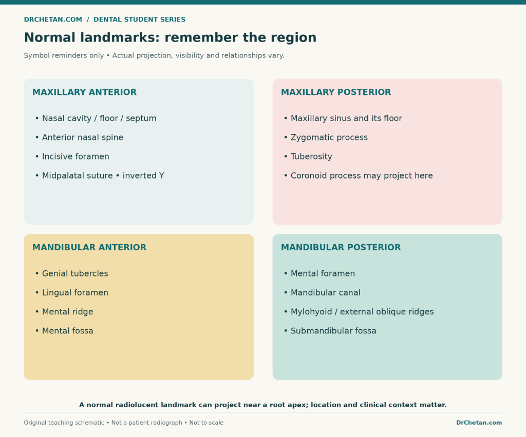
Figure 4. A regional memory guide, not a composite anatomical radiograph. Actual visibility and relationships vary.
Examine the crown and restorations
Trace the visible tooth outline, contacts, enamel, dentin, and any restorations. Ask where a suspicious radiolucency is located and whether image quality permits a dependable assessment.
A proximal radiolucency may support a caries finding, but it does not by itself establish surface cavitation, lesion activity, or a complete treatment decision. Depth and extent can be under- or over-represented by projection and other factors. Appropriate clinical examination remains necessary.
For proximal caries, a suitably selected bitewing may provide information that an overlapped IOPA does not. This is a question of indication and geometry, not a rule that every periapical requires an extra exposure.
Note the radiographic appearance of restorations, crowns, posts, or other materials without assuming their precise composition from radiopacity alone. A dark line near a restoration can represent several things, including a true defect, an interface, projection, or an optical effect.
Cervical burnout can resemble cervical or root caries. Its location and appearance should prompt correlation with the tooth surface and adjacent findings rather than an automatic caries label. The broader lesson is that contrast effects and anatomy can create false-positive impressions.
Follow the pulp space and every visible root
Review the chamber and canals from crown towards apex. Note apparent narrowing, abrupt changes, curvature, open apices, resorptive changes, fracture-like lines, or radiopaque treatment materials.
Use cautious language:
- “Two roots are visible on this projection” is different from proving that no additional root exists.
- “The canal becomes indistinct in the middle third” is a description; it does not identify the cause without further assessment.
- “No fracture line is visible” is different from excluding a fracture.
- “The root filling projects close to the radiographic apex” does not prove that every canal is disinfected or that the tooth is symptom-free.
Root and canal anatomy can be concealed by overlap. The radiographic apex is also not a direct marker of the exact position of every apical foramen. An image alone is not a complete working-length procedure or a test of treatment success.
Compare age and development. A wide canal and open apex in an immature permanent tooth may be developmental rather than destructive. The interpretation changes if the same apparent shape is associated with unexpected symptoms, trauma, or other abnormal findings.
Assess periodontal support systematically
Look at crestal levels, the pattern and distribution of visible bone loss, the ligament space, lamina dura, furcation regions, and any radiopaque deposits that may be calculus.
Describe whether visible loss appears broadly horizontal or has an angular component. Consider image projection before estimating severity. Facial and lingual defects can be concealed by the superimposed tooth and bone.
A radiograph does not measure pocket depth, bleeding on probing, or clinical attachment level. Likewise, absence of obvious radiographic bone loss does not exclude gingival inflammation or early disease. Combine the image with periodontal probing, recession, mobility, symptoms, and the rest of the examination.
An IOPA is a view of the included area. It cannot establish that the rest of the patient’s dentition has the same periodontal condition.
Assess the periapical region without jumping to “abscess”
Start by tracing the root outline, apical ligament space, lamina dura, and surrounding trabeculation. Then assess any focal change relative to the root and regional anatomy.
Possible findings include ligament-space widening, interruption of a previously definable socket outline, radiolucency, radiopacity, or mixed change. Each is a finding, not a complete diagnosis.
A normal-looking periapical area does not rule out pulpitis or every early apical inflammatory process. Changes may not yet be radiographically apparent, or they may be obscured. The history, clinical tests, and image must be interpreted together.
Why a radiolucency is not a histological diagnosis
A periapical radiolucency can be associated with several inflammatory or non-inflammatory conditions. Routine radiographic appearance cannot reliably distinguish an abscess, granuloma, and radicular cyst.
A round shape, a corticated border, or a large apparent size may influence a differential diagnosis, but none alone proves a cyst. Clinical context determines whether an inflammatory explanation is plausible; tissue diagnosis may be relevant in selected circumstances, rather than being required for every routine lesion.
Similarly, a positive sensibility response from a nearby tooth should not be ignored merely because a radiolucency projects beside its apex. Confirm the response and reassess the possible origin of the finding.
Describe an abnormality before interpreting it
Use a structured description:
| Feature | Useful questions |
|---|---|
| Site | Which region and relationship to which tooth, root, or landmark? |
| Extent and size | Fully included or cut off? Measurable on this calibrated image, or only approximately described? |
| Shape | Round, ovoid, irregular, or another form? |
| Boundary | Well defined, corticated, partly defined, or ill defined? |
| Internal appearance | Radiolucent, radiopaque, or mixed? Uniform or heterogeneous? |
| Effects | Displacement, resorption, altered cortical outline, or other visible effect? |
| Associated findings | Caries, restorations, root treatment, periodontal changes, or a normal landmark? |
A well-defined boundary does not guarantee harmlessness. An ill-defined boundary is not a diagnosis of malignancy. Unexpected destruction, sensory symptoms, swelling, or a pattern inconsistent with the presumed dental cause warrants appropriate further assessment.
Avoid measurements on an uncalibrated screenshot as though they were true anatomical dimensions. Projection and magnification matter. When a border leaves the image, report that the full extent cannot be assessed.
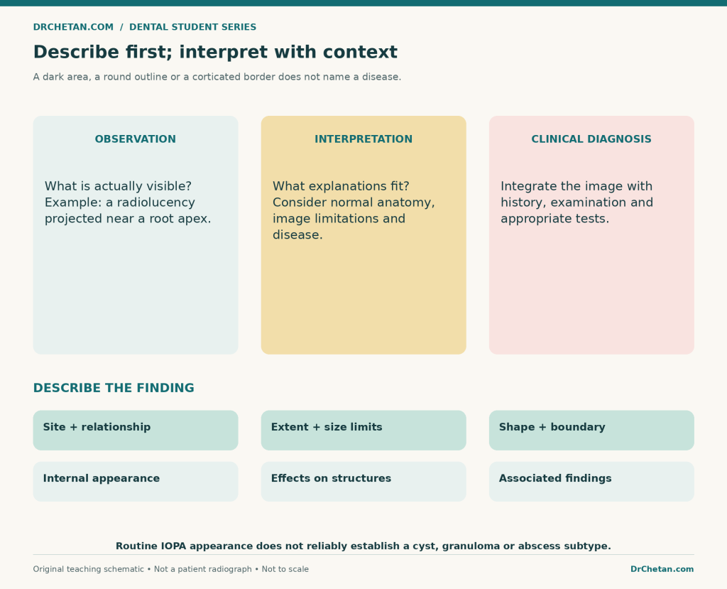
Figure 5. Observation, interpretation, and diagnosis are related but distinct steps. A descriptive report can be useful even when certainty is limited.
Three clinical image exercises
These examples retain their original image content. Existing source annotations remain in place. The teaching notes are not a retrospective diagnosis of the individual patient.
Exercise 1: canal anatomy near the mental foramen
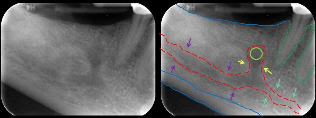
Clinical image A. “Mandibular Incisive Canal Highlighted,” DRosenbach, via Wikimedia Commons, CC BY-SA 3.0. Source and original image. Reproduced without alteration; the coloured highlighting belongs to the source author.

Compare the unmarked panel with the highlighted panel. The source identifies the region where the mandibular canal continues towards the incisive canal near the mental foramen. Follow the underlying radiolucent course and its bordering lines, rather than memorising the colour alone.
This is a regional anatomy example with limited dental coverage. It is not an ideal complete-tooth IOPA for every diagnostic purpose. The coloured lines are explanatory annotations, not anatomical boundaries measured directly from a three-dimensional dataset.
Practice answer: “The provided paired image demonstrates a radiolucent canal region with source highlighting near the mental foramen. Normal neurovascular anatomy must be considered before interpreting every nearby radiolucency as a lesion.”
Exercise 2: molar periapical radiolucencies
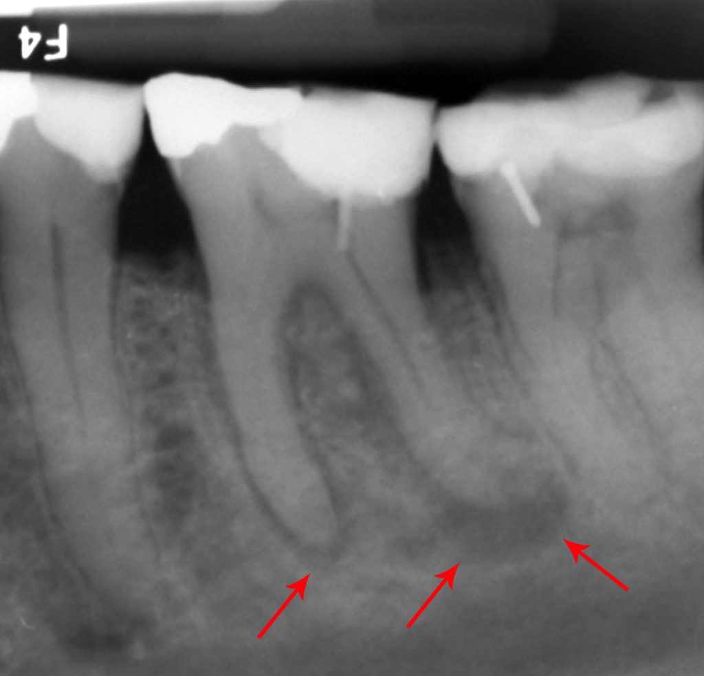
Clinical image B. “Abscessed tooth periapical radiograph,” Coronation Dental Specialty Group, via Wikimedia Commons, CC BY-SA 3.0. Source and original image. Reproduced without alteration; red arrows are present in the source.

First inspect the crowns and restorations, then trace the roots and apical areas. The source’s arrows direct attention towards radiolucent regions associated with the molar root ends.
The source describes the tooth as FDI 36 and uses the term abscess. For image-reading practice, start with periapical radiolucencies associated with the molar roots. The source’s clinical label is not something that the arrows alone independently prove.
Practice answer: “The image demonstrates periapical radiolucent changes associated with the roots of the restored molar identified by the source as 36. An inflammatory origin is a consideration, requiring correlation with the history, pulp and apical tests, periodontal findings, and prior treatment.”
Do not invent symptom duration, test responses, drainage, or a microscopic diagnosis.
Exercise 3: developing dentition
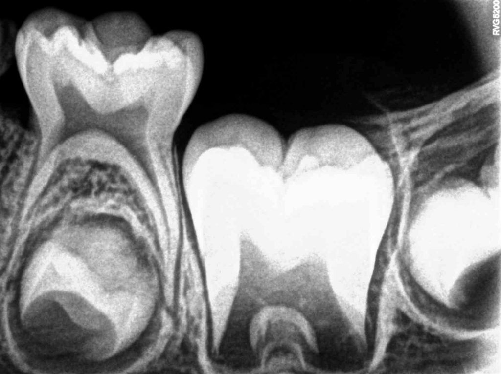
Clinical image C. “Intraoral Periapical Radiograph … Tooth 75 … 35, 36 and 37,” Nizil Shah, via Wikimedia Commons, CC BY-SA 4.0. Source and original image. Reproduced without alteration.

The source identifies primary tooth 75 and developing permanent teeth 35, 36, and 37, including 35 below 75. Review the relationship between the primary roots and developing successor, the mineralised crown outlines, and the radiolucent spaces around developing structures.
Not every dark space around a developing tooth is a cyst, and incomplete root formation is not automatically resorption. Equally, identifying normal development does not establish that every other finding in the image is normal.
Practice answer: “The image illustrates primary and developing permanent dentition as identified by the source. Interpretation must account for developmental stage; this view should not be assessed using an adult complete-root template.”
Paediatric imaging should answer an individual clinical question with age-appropriate selection and optimisation.
Two fictional interpretation problems
Case 1: severe symptoms, little visible periapical change
A patient reports tooth pain, but the included periapical bone has no convincing focal change on an adequate image. A student concludes, “The tooth is healthy.”
The error is treating a negative image as a complete pulp assessment. A better report separates the radiographic observation from the clinical question: “No definite focal periapical radiolucency is visible on this projection; pulpal status requires clinical assessment.”
The next information depends on the history and examination, including appropriate sensibility and apical tests. It is not automatically a CBCT scan.
Case 2: an apex is outside the image
A student writes, “No periapical lesion,” although the root end and adjacent bone are excluded.
The correct limitation is: “The apex and adjacent periapical region are not fully recorded; this region cannot be adequately assessed.” Whether another image is justified depends on the clinical need and existing information. The response is neither unsupported reassurance nor an automatic repeat without considering the indication.
Write a concise report
A useful student report includes identity and region, image adequacy, the relevant positive and negative findings, an appropriately qualified impression, and the information needed to resolve uncertainty.
Here is a fictional report example:
“Periapical image of the mandibular left molar region, with orientation verified from the clinical record. The tooth of interest and surrounding apical bone are included. There is a radiolucent change associated with the distal root apex of 36, with local alteration of the normally definable socket outline. The full visible image has been reviewed. An inflammatory periapical process is a consideration; correlate with pulp sensibility testing, percussion/palpation, periodontal assessment, symptoms, and treatment history. The radiograph does not establish a cyst, granuloma, or abscess subtype.”
Do not copy this as a report for the clinical photograph above: it is an invented writing example. Real reports must match the actual image and examination.
Avoid statements such as “no pathology” when only a specific, limited question has been assessed. “No definite radiographic evidence of…” followed by the assessed finding and any limitation is often more accurate.
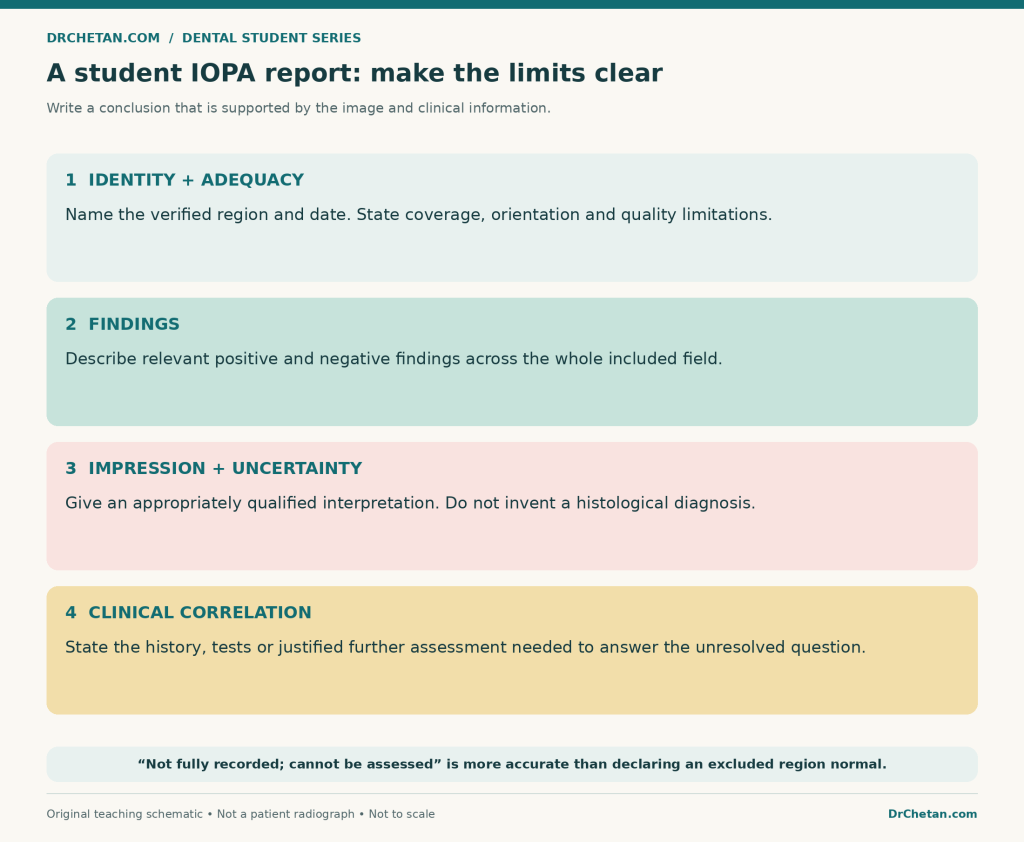
Figure 6. Report what is assessable, say what remains uncertain, and relate further assessment to a specific question.
When is another view or modality useful?
Further imaging is justified when it is likely to answer a relevant unresolved clinical question. An altered projection may separate overlapping structures. A bitewing may better address a particular proximal-surface question. In selected situations, CBCT can provide information that two-dimensional images cannot.
CBCT is not a routine upgrade for every painful tooth, normal-looking apex, or difficult exam answer. The 2025 AAE/AAOMR position statement stresses clinical evaluation and selective use when the imaging need cannot reasonably be met by lower-dose two-dimensional radiography.
If the finding is unexpected, incompletely characterised, or outside your interpretive competence, seek appropriate supervision or an oral and maxillofacial radiology opinion. Review the whole acquired image, not just the structure that motivated it.
Twenty viva questions with explained answers
- What does IOPA mean? Intraoral periapical radiograph: a projection intended to show the tooth and surrounding periapical tissues.
- Why should quality be assessed first? Missing anatomy, overlap, distortion, or poor detail can invalidate the conclusion.
- What apical coverage is commonly taught? About 2–3 mm of surrounding bone beyond the apex, while including the actual region of interest.
- Can a cropped image establish the side reliably? Not always. Verify orientation and acquisition information before assigning right, left, or a tooth number.
- How is labial mounting viewed? As though facing the patient; the patient’s right appears on the viewer’s left.
- What is radiolucency? A relatively darker appearance on the usual display, not a diagnosis of disease.
- Which tooth tissue normally appears most radiopaque? Enamel is more radiopaque than dentin under usual viewing conditions.
- Can normal cementum usually be distinguished from dentin? No; it should not be confidently labelled as a separate thin layer on a routine image.
- How do PDL space and lamina dura differ? The space is relatively radiolucent; the socket’s lamina dura appears relatively radiopaque.
- Does an indistinct lamina dura segment prove pathology? No. Projection, anatomy, image quality, and other findings must be considered.
- What landmark can mimic a premolar periapical lesion? The mental foramen can be superimposed near a premolar apex.
- Does apparent contact with the sinus prove root penetration? No. A two-dimensional projection cannot establish that three-dimensional relationship alone.
- What commonly causes contact overlap? Unsuitable horizontal beam alignment, with tooth and receptor positioning also relevant.
- Can adjusting brightness restore a missing apex? No. Display changes cannot recover anatomy outside the captured field.
- Does an IOPA establish pulp vitality? No. It images structural relationships, not direct pulpal blood flow.
- Can pulpitis occur without a visible apical radiolucency? Yes. Clinical assessment remains necessary.
- Does a round corticated radiolucency prove a radicular cyst? No. Routine appearance cannot provide that histological certainty.
- Does radiographic proximal caries automatically prove cavitation? No. Correlate with appropriate clinical assessment.
- Can radiographs replace periodontal probing? No. Pocket depth, bleeding, attachment findings, and other clinical information are separate.
- When should additional imaging be considered? When a specific unresolved clinical question warrants it, using an appropriate modality and justified exposure.
Leave a Reply