An illustrated guide for dental students, organised by department, with common look-alikes, photograph references, and viva questions.
Recognising a dental instrument means more than remembering its name. You should be able to point to the working end, describe what makes it different from a similar instrument, and connect that design with its intended use.
A shiny handle is rarely the best starting point. The decisive feature may be a millimetre scale, a spoon-shaped blade, a rounded toe, a file’s flutes, or the gripping surface inside a pair of jaws. Once you learn to inspect those features systematically, an unfamiliar tray becomes much less intimidating.
This guide introduces common instrument families across diagnosis, conservative dentistry, periodontology, endodontics, oral surgery, prosthodontics, and orthodontics. Instruments overlap between departments: grouping them here is a study aid, not a claim that an instrument belongs exclusively to one specialty.
The diagrams are original teaching schematics. The credited photographs are online reference images and require an internet connection; they are not AI-generated identification pictures. Instrument use below is described at an identification level. Learning the name does not replace supervised training or the instructions for the particular device.
In this guide
- First inspect the handle, shank, and working end
- A reliable sequence for an instrument spotter
- 1. Diagnostic and examination instruments
- 2. Conservative dentistry and restorative instruments
- 3. Periodontal instruments
- 4. Endodontic instruments
- 5. Oral surgery instruments
- 6. Prosthodontic and laboratory instruments
- 7. Orthodontic instruments
- Commonly confused instruments: rapid revision table
- How to study from photographs and actual instruments
- Four worked instrument spotters
- Twenty viva questions with explained answers
First inspect the handle, shank, and working end
For most conventional hand instruments, identify three basic regions:
- Handle: the part held by the operator. Its diameter, texture, and material influence grip and control, but similar handles can carry very different ends.
- Shank: the connection between handle and working end. Bends and offsets help provide access and position the working end.
- Working end: the part that contacts the tooth, material, tissue, wire, or another object. This may be a blade, nib, point, spoon, jaw, or other specialised form.
For a hinged instrument, also inspect the joint, jaws, and locking mechanism where present. A needle holder and a haemostat can have similar finger rings and ratchets; their jaws and intended function are more informative than the rings alone.
Instruments may be single-ended or double-ended. A double-ended design does not automatically mean that both ends are identical or can be used in the same way. Turn the instrument to inspect the face, side, and tip rather than identifying it from one silhouette.
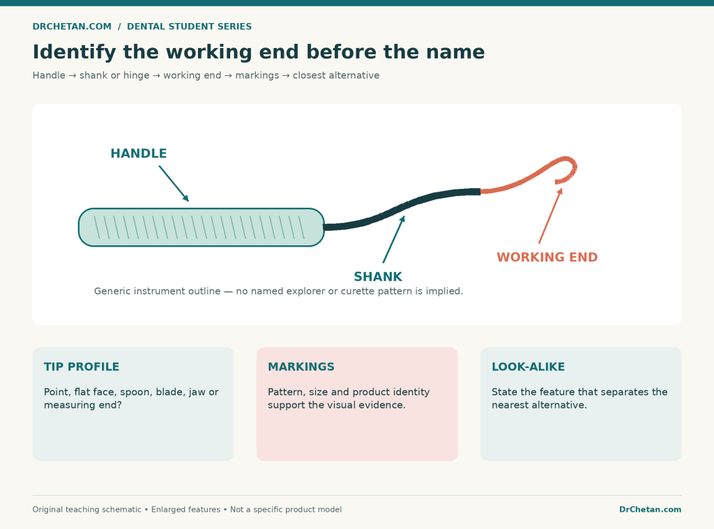
Figure 1. A consistent inspection sequence. This is an original study framework, not an official examination marking scheme.
A reliable sequence for an instrument spotter
- Choose the broad family. Is it for examination, cutting, carrying material, condensing, grasping, measuring, bending, or another task?
- Inspect the working end closely. Look for calibration marks, cutting edges, concavity, serrations, a pointed or flat tip, or a specialised jaw pattern.
- Inspect the shank or hinge. Decide how the bend or mechanism helps provide access or perform the task.
- Read the markings. Note the manufacturer’s name, pattern number, size, length, or other identification.
- Compare the nearest alternative. State the feature that rules out the instrument students commonly confuse with it.
A useful viva answer is: name ? identifying features ? principal use ? closest look-alike. If a pattern cannot be established from the available view, identify the family and explain what additional view or marking you need.
1. Diagnostic and examination instruments
Mouth mirror
Recognise the reflective head attached to a slender shank and handle. It supports indirect vision, illumination, and appropriate soft-tissue retraction. Mirror designs vary, including the location of the reflecting surface, so the head is more informative than handle colour.
Dental explorer
An explorer has a fine, pointed working end. Different patterns are designed for different access needs; the familiar curved shepherd’s-hook pattern is only one example. Its role is tactile assessment of surfaces and irregularities, including deposits and restoration margins where appropriate.
Do not define an explorer as an instrument that must be pushed forcefully into every suspicious pit to make a caries diagnosis. Recognition of the instrument and selection of an appropriate diagnostic method are separate questions.
Periodontal probe
A periodontal probe is a measuring instrument. Its slender working end has a defined marking pattern; its tip is comparatively blunt rather than a sharp explorer point. UNC, Williams, and ball-ended screening probes have different features, so identify the particular scale rather than assuming that every dark band equals one millimetre.
Cotton or dressing pliers
These are tweezer-like instruments used to carry and retrieve small items. College-pattern pliers commonly have angled tips; locking and non-locking variants exist. They are not extraction forceps simply because both names can include the word “forceps.”

Photograph A. Periodontal probe above and explorer below, as identified by the original source. Credit: Coronation Dental Specialty Group, Wikimedia Commons source, CC BY-SA 3.0. Shown without local alteration; the online image may not load on every network.
What to compare: the probe’s measuring marks and the explorer’s fine point. Neither should be identified from the handle alone.
2. Conservative dentistry and restorative instruments
Many restorative instruments have similar metal handles. Sort them by whether the end cuts, carries, shapes, or compacts a material. Manufacturer sets commonly contain excavators, burnishers, pluggers, placement instruments, margin trimmers, and carvers, but their pattern numbers are not a universal naming system.
| Instrument family | Recognition feature | Principal use or role |
|---|---|---|
| Spoon excavator | Small spoon-like blade with a concave face and cutting edge | Hand excavation of appropriate softened tooth material |
| Enamel chisel | Blade with a defined cutting edge; straight or angled patterns | Controlled cutting or planing of enamel in suitable applications |
| Enamel hatchet | Hatchet-like blade geometry and a cutting edge positioned differently from a chisel pattern | Cutting or refining tooth structure where indicated |
| Gingival margin trimmer | Curved, modified cutting blade, commonly supplied in complementary patterns | Refinement of selected gingival enamel margins |
| Plastic filling or composite placement instrument | Paddle, blade, or other placement end; may have a surface coating | Carrying, adapting, or shaping an appropriate restorative material |
| Condenser or plugger | A compacting end with a defined terminal face; round or other outlines | Condensing or adapting the material for which it is intended |
| Ball burnisher | Smooth, rounded ball-like working end | Burnishing and contouring in compatible restorative applications |
| Hollenback-type carver | Thin, shaped blade with cutting edges | Carving contour and removing excess material in suitable restorations |
| Discoid–cleoid carver | Disc-like end paired with a pointed, shaped carving end | Carving anatomical form in appropriate restorative materials |
| Cement spatula | Broad mixing blade rather than a tiny intraoral nib | Mixing compatible dental cements on the recommended surface |
| Amalgam carrier | Barrel or delivery end with an expressing mechanism | Carrying and dispensing amalgam; not the same task as condensation |
Excavator, burnisher, condenser, or carver?
Ask what the tip is built to do. A spoon excavator has a concavity and a cutting edge. A ball burnisher presents a smooth rounded surface. A condenser has a terminal face for compaction, while a carver has a blade for shaping or removing excess material.
Do not infer cutting ability simply because the end looks shiny or pointed in a photograph. Rotate the actual instrument: a blade viewed edge-on can look like a narrow point, while a concavity may disappear when viewed from the back.
The term plastic filling instrument refers to use with a material in a plastic or workable state; it does not mean the instrument itself must be made from plastic. Likewise, an instrument described as a plugger in a restorative tray is not automatically the same design as an endodontic plugger.
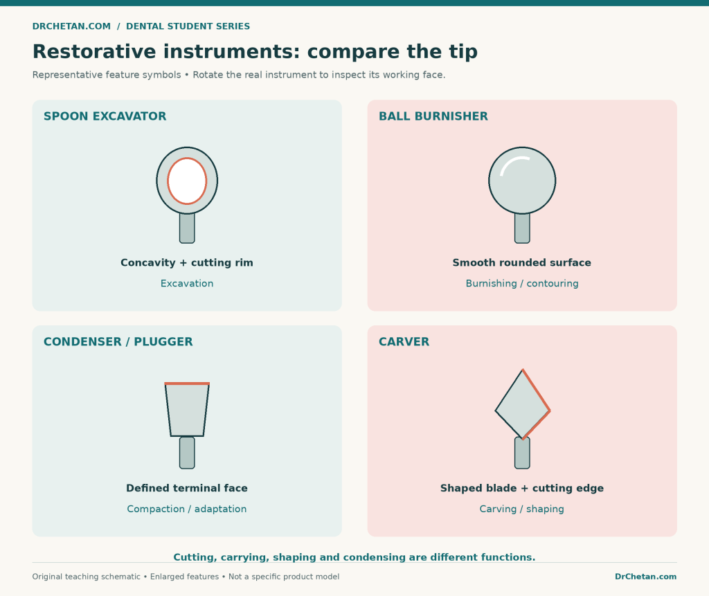
Figure 2. Representative working-end features, deliberately enlarged. These symbols illustrate a spoon, smooth ball, terminal face, and blade; they are not exact drawings of a named manufacturer’s pattern.
Isolation and matrix instruments
| Item | Recognition feature | Main distinction |
|---|---|---|
| Rubber dam punch | Punching mechanism with a selectable hole-size arrangement in common designs | Makes holes in the dam sheet |
| Rubber dam clamp forceps | Tips designed to engage the clamp’s holes, with a mechanism to open and control it | Carries and opens a clamp; does not punch the sheet |
| Rubber dam clamp | Spring-like retaining device with jaws and a bow | Retains the dam around an appropriate tooth |
| Tofflemire-type matrix retainer | Mechanical head and adjustment components that hold a compatible band | Retains a circumferential matrix band |
| Matrix band and wedge | A band provides a temporary restorative wall; a wedge has a different supporting role | They are components of a system, not interchangeable objects |
These items are found in restorative teaching setups, but designs and selection vary. Identify the device and its role before discussing its assembly in a practical session.
Photograph practice: compare the manufacturer’s GDC restorative cassette and named contents. These are linked product references; their photographs are not reproduced as original DrChetan.com images.
3. Periodontal instruments
Sickle scaler
A conventional sickle scaler has a triangular cross-section, with two cutting edges and a pointed tip. Its back is also angular. Sickle patterns can have straight or curved blades and different shank arrangements. The classic introductory use is removal of supragingival calculus.
Universal curette
A conventional universal curette has a rounded toe and back, with two usable cutting edges. Its blade face is conventionally described as perpendicular to the terminal shank. The rounded profile differs from a sickle’s triangular cross-section.
Gracey curette
A standard Gracey curette is area-specific. Its blade face is offset relative to the terminal shank, conventionally described as about 70°, with the lower cutting edge intended for use. It also has a rounded toe and back. The shank and blade arrangement help distinguish it from a universal curette.
The 70° and 90° descriptions refer to instrument design relationships. They are not instructions to place every instrument against a tooth at those angles. Clinical adaptation and working angulation are separate concepts learned with supervised instrumentation.
| Feature | Conventional sickle scaler | Universal curette | Standard Gracey curette |
|---|---|---|---|
| Cross-sectional family | Triangular | Semicircular | Semicircular |
| Tip or toe | Pointed tip | Rounded toe | Rounded toe |
| Back | Angular | Rounded | Rounded |
| Cutting-edge use | Two edges | Two edges | Lower edge of each working end |
| Design emphasis | Commonly supragingival calculus removal | Broad surface application | Area-specific access and adaptation |
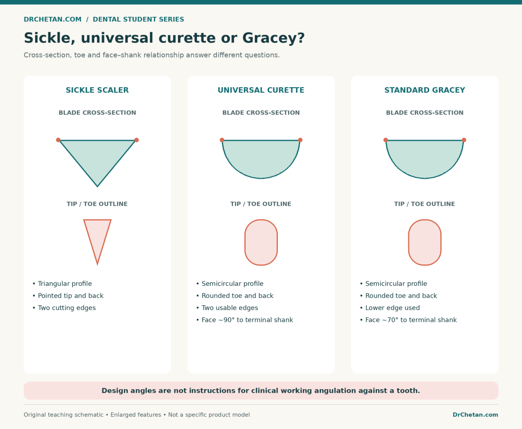
Figure 3. Cross-section and toe are different views. A semicircular cross-section alone cannot distinguish a universal curette from a Gracey; inspect the face–shank relationship and the identified pattern.

Photograph B. Scaler working-end close-up. Credit: DRosenbach, Wikimedia Commons source, released into the public domain. Use the source view to inspect the actual end; no exact pattern number is assigned here.
When learning Gracey patterns, use the map supplied with your teaching set. Standard and modified designs coexist, including extended shanks and shortened blades. A colour ring may identify a local set or handle system; it is not a substitute for confirming the pattern.
4. Endodontic instruments
Begin by separating exploration and preparation instruments from obturation instruments and measuring accessories. A fine metal instrument is not necessarily a file, and a similar coloured handle does not prove that two instruments have the same function.
| Instrument or item | Recognition clue | Principal role |
|---|---|---|
| DG16-type endodontic explorer | Fine angled points suited to the pulp-chamber region | Exploration and location of canal entrances in the appropriate setting |
| K-file | Fine fluted working portion, with type and size information on the product | Canal negotiation and preparation within the selected technique |
| K-reamer | Commonly fewer, more widely spaced flutes than a comparable conventional K-file | Reaming-related canal preparation |
| Hedström or H-file | Machined, pronounced cutting-flute form in conventional designs | Efficient filing action; not interchangeable with a continuously rotating file |
| Barbed broach | Barbs projecting from a fine shaft | Engaging and removing appropriate pulp tissue; not a canal-shaping substitute |
| Endodontic spreader | Smooth tapered working end that terminates in a point | Creating space during an appropriate lateral compaction technique |
| Endodontic plugger | Smooth working portion ending in a flat or blunt terminal face | Compaction, including vertical compaction where appropriate |
| Endodontic measuring block or ruler | Calibrated measuring arrangement | Setting or checking instrument-related measurements |
The file and reamer distinctions above concern conventional families. Manufacturing methods, cross-sections, alloys, tapers, and motion requirements vary by product. Confirm the instrument’s packaging and instructions rather than extending one old textbook diagram to every modern file system.
K-file, reamer, and H-file: what should you actually compare?
Inspect the flutes, not just the plastic handle. Compare instruments of a similar size and inspect the full working portion where possible. A conventional reamer’s relatively open flute spacing is a useful clue, but a low-resolution photograph may not establish the type reliably.
Do not memorise “every K-file is square in cross-section” as an exceptionless rule. Even a single manufacturer’s range may use different cross-sections for different sizes or designs. A catalogue diagram describes that product family; it is not a universal licence to infer the metallurgy of an unidentified file.
Also separate file type, size, length, taper, and motion system. A handle colour may encode size within a specified system. It does not, by itself, tell you whether the instrument is a K-file, an H-file, or something motor-driven.

Photograph C. Left to right: Lentulo spiral, reamer, K-file, H-file, as identified in the original source. Credit: Metju12, Wikimedia Commons source, released into the public domain. The original is 863 × 565 pixels; enlarging it cannot reveal detail absent from the photograph.
Spreader versus plugger
This is a high-yield comparison because both can be smooth, slender instruments. Follow the taper all the way to the end: the spreader is pointed, while the plugger has a terminal face. Do not confuse a shadow or an oblique photograph with the true shape of the tip.
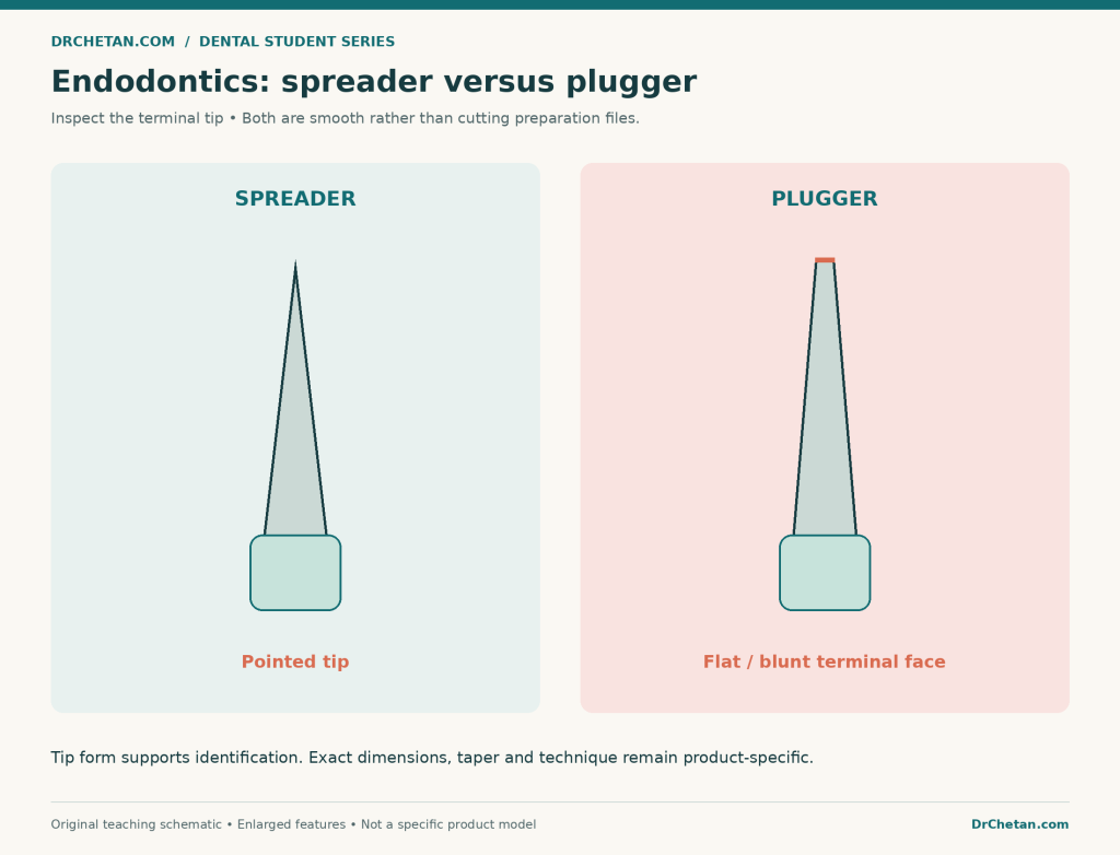
Figure 4. The terminal tip is the deciding feature in this simplified comparison. Dimensions are exaggerated and no manufacturer size or taper is implied.
5. Oral surgery instruments
Think in functional groups: instruments for cutting, tissue reflection, tooth or root manipulation, retraction, bone work, and closure. The department’s tray and the manufacturer’s catalogue help establish the exact named pattern.
| Instrument family | What to inspect | Principal role |
|---|---|---|
| Scalpel handle and blade | Handle’s blade-fitting region and the shape/markings of the mounted blade | Surgical incision with a compatible blade |
| Periosteal elevator | Broad, relatively flat or shaped end for a tissue plane | Elevating or reflecting periosteal tissue in appropriate surgery |
| Dental tooth/root elevator | More substantial handle and a blade designed for tooth/root manipulation | Luxation or elevation within the selected technique |
| Extraction forceps | Paired beaks, hinge, handle form, and beak orientation | Grasping and delivering an appropriate tooth or root |
| Tissue forceps | Tweezer-like jaws, sometimes with teeth or a specific atraumatic gripping pattern | Grasping and stabilising tissue according to the design |
| Haemostat or artery forceps | Hinged clamping instrument, commonly with a ratchet and serrated jaws | Clamping appropriate tissue or vessels as indicated |
| Needle holder | Gripping jaws designed to control a suture needle; many conventional patterns have short, sturdy jaws | Holding and guiding a needle during suturing |
| Surgical scissors | Cutting blades rather than a clamping surface | Cutting tissue or sutures according to the particular design |
| Retractor | A broad or contoured surface for holding tissue aside | Retraction to support access and visibility |
| Bone rongeur | Opposing bone-cutting jaws, often with a spring mechanism | Removing small portions of bone where indicated |
| Bone file | Rasp-like cutting surface | Refining bone surfaces in appropriate procedures |
Periosteal elevator versus tooth elevator
The shared word “elevator” describes a broad mechanical idea, not identical uses. Inspect the end and the structure it was designed to engage. A broad tissue-reflecting end and a robust tooth/root-manipulating blade should not be treated as substitutes simply because both are attached to handles.
Needle holder versus haemostat
Both may have rings, a hinge, and a locking ratchet. Conventional needle holders commonly have shorter, more robust gripping jaws, often with a textured gripping surface suited to the needle. Many haemostats have longer, narrower serrated jaws for clamping.
These are recognition tendencies, not absolute rules: micro instruments and special patterns can look different. Confirm the jaw face and product identification. Gold-coloured handles or inserts alone do not establish the name, and the presence of a ratchet does not make every instrument a haemostat.
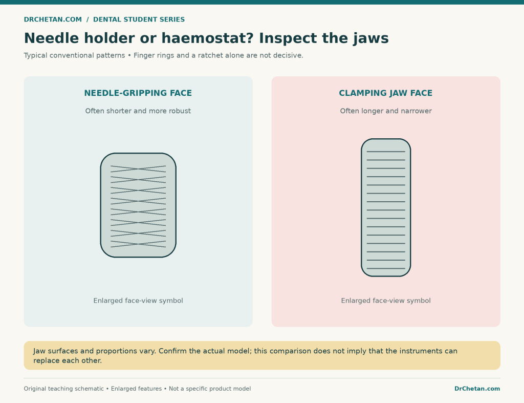
Figure 5. Typical conventional jaw characteristics, shown as simplified face views. Special patterns vary; this is not a precise model drawing or a substitution guide.
How should students identify extraction forceps?
Inspect the relationship between handles and beaks, the width and contour of both beaks, and any asymmetry. Then compare the instrument with the relevant arch and tooth/root anatomy in the manufacturer’s illustrated catalogue or your department’s set.
Do not determine “right” or “left” by placing an unfamiliar pair on a desk and applying a remembered rule without first orienting the design. Pattern numbering and naming vary, and a root-forceps variant may resemble a broader tooth-forceps family from one angle. In a practical examination, justify the identification from the actual beaks and confirmed pattern rather than guessing a number.

Photograph D. Extraction-forceps set for comparing overall forms. Credit: Bsz surgico, Wikimedia Commons source, CC BY-SA 3.0. Individual tooth assignments are not inferred from this group photograph.
6. Prosthodontic and laboratory instruments
Recognise whether an item is for impression making, material mixing, wax work, measurement, or clinical adjustment. Some items are devices or accessories rather than hand instruments in the narrow sense, but they commonly appear in identification exercises.
| Instrument or item | Recognition feature | Principal role |
|---|---|---|
| Stock impression tray | Arch-shaped carrier with a handle; may be perforated or non-perforated | Supporting and carrying a compatible impression material |
| Alginate mixing spatula | Broad blade suited to mixing in a flexible bowl | Mixing an appropriate hydrocolloid material |
| Cement spatula | More rigid mixing blade in common patterns | Mixing compatible cements; identify the exact blade and intended material |
| Wax knife or wax spatula | Blade or shaped modelling end | Cutting, manipulating, and modelling wax |
| Le Cron-type wax carver | Commonly a pointed end paired with a spoon-like modelling end | Wax modelling and carving |
| Articulating-paper holder | Gripping jaws shaped to retain a paper strip | Carrying and positioning articulating paper |
| Gingival cord packer | Small packing end, with surface texture varying by pattern | Placing retraction cord in an appropriate procedure |
A perforated tray is not automatically suitable for every impression material. Material compatibility, retention requirements, adhesive use, tray rigidity, and the intended impression determine selection. For identification, start with the tray’s arch form, dimensions, handle, and retentive features; discuss material-specific selection separately.

Photograph E. Maxillary impression tray. Credit: Dentina54, Wikimedia Commons source, CC BY 4.0. No local alteration is included.
7. Orthodontic instruments
The most useful first distinction is gripping versus bending versus cutting. Instruments in all three categories may look like pliers, but their jaw surfaces and intended loads differ. [14,15]
| Instrument family | Recognition clue | Principal role |
|---|---|---|
| Weingart utility pliers | Slender, often angled gripping beaks with serrated contact surfaces | Grasping and guiding archwires and components |
| Bird-beak pliers | Common conventional pattern pairs a round/conical beak with a pyramidal or flat-sided beak | Forming bends or loops in compatible wire |
| Adams pliers | Relatively flat, squared working-beak form in conventional designs | Bending and handling wire, including clasp-related work |
| Mathieu ligature pliers | Spring/palm-operated locking design rather than ordinary finger rings | Holding and placing appropriate ligatures or elastics |
| Distal-end cutter | Cutting head designed for distal archwire access; some patterns retain the cut segment | Cutting an archwire end within the device’s specified limits |
| Ligature cutter | Fine cutting tips intended for specified ligature wire | Cutting compatible ligatures; not a general heavy-wire cutter |
| Hard-wire cutter | More substantial cutting arrangement designed for a specified wire capacity | Cutting the compatible harder or larger wire range |
| Band-removing pliers | Specialised opposing ends, commonly including a protective support component | Removing an orthodontic band according to the design |
Photograph practice: use GDC’s named orthodontic pliers and the HuFriedyGroup orthodontic setup reference. Compare the actual jaw faces, not only the handle silhouette.
Distal-end cutters are not all cut-and-hold instruments
Manufacturers offer both retaining and non-retaining designs. Verify the exact model before describing it as “cut and hold.” Wire capacity is also model-specific: a familiar-looking cutter cannot be assumed to cut every material or thickness, and a fine ligature cutter should not be identified as a universal archwire cutter.
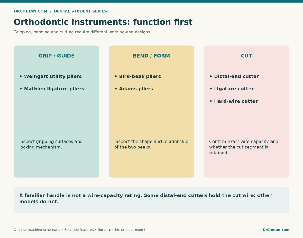
Figure 6. Function first, then the exact jaw and model. This map contains no universal wire-capacity claim.
Commonly confused instruments: rapid revision table
| Pair | The useful distinction |
|---|---|
| Explorer and periodontal probe | Fine assessment point versus a defined measuring scale and relatively blunt tip |
| Spoon excavator and ball burnisher | Concave cutting spoon versus a smooth rounded surface |
| Condenser and carver | Terminal compaction face versus a shaping blade |
| Sickle scaler and curette | Pointed triangular profile versus a rounded toe/back with a semicircular cross-section |
| Universal and Gracey curettes | Two usable edges and conventional perpendicular face relationship versus area-specific offset design using the lower edge |
| K-file and H-file | Confirm the fluted design and product identification; handle colour alone is insufficient |
| Barbed broach and preparation file | Projecting barbs for tissue engagement versus a cutting preparation design |
| Endodontic spreader and plugger | Pointed tip versus a flat/blunt terminal face |
| Periosteal and tooth/root elevators | Tissue-reflecting end versus a tooth/root-manipulating design |
| Needle holder and haemostat | Needle-gripping jaws versus a clamping design; rings and ratchets alone do not decide |
| Rubber dam punch and clamp forceps | Hole-making mechanism versus clamp-engaging tips |
| Weingart and bird-beak pliers | Gripping/guiding design versus a wire-forming beak arrangement |
| Distal-end and ligature cutters | Different intended wire positions and capacities; confirm the individual model |
How to study from photographs and actual instruments
Use photographs in pairs: one showing the full instrument and another showing the working end from the most useful angle. A whole tray is helpful for orientation, but often too small to show an explorer point, a curette’s toe, or a file’s flute geometry.
For each instrument, make a four-line note: name, two observable features, principal use, closest look-alike. Then cover the label and identify it from another view. If the identification depends on remembering a coloured handle rather than the working end, revisit the comparison.
Practice with clean teaching instruments under the department’s handling rules. Use photographs or a magnifier for fine details; never test sharpness against your fingers. A blunt, worn, damaged, or distorted end can differ from the catalogue image and should not be treated as the ideal pattern.
Finally, keep instrument processing separate from visual cleanliness. CDC guidance distinguishes cleaning from sterilisation; critical instruments and most heat-tolerant semicritical dental instruments require heat sterilisation, with manufacturer instructions governing the appropriate process. Single-use items are not reclassified as reusable simply because they look intact.
Four worked instrument spotters
Spotter 1: the familiar handle is misleading
You are shown two slender instruments with similar handles. One has a graduated working end; the other has an ungraduated fine curved point. The first is consistent with a periodontal probe and the second with an explorer. Explain the measuring marks and tip form rather than saying that one “looks like a dental probe,” a phrase that can be used ambiguously.
Spotter 2: a rounded periodontal end
A double-ended instrument has a rounded toe and back. That supports a curette family identification, but does not by itself establish a Gracey. Next inspect the terminal shank, blade face relationship, and pattern marking. The correct follow-up is further comparison, not an immediate guess based on a coloured ring.
Spotter 3: two smooth endodontic instruments
Both have tapered working ends. One terminates in a point; the other has a visible terminal face. The first is consistent with a spreader and the second with a plugger. If the tip is hidden by the photograph, say that the view is insufficient and request or examine another view.
Spotter 4: two ring-handled surgical instruments
Both have a hinge and ratchet. One has short robust needle-gripping jaws; the other has longer clamping jaws. In conventional patterns this supports needle holder versus haemostat. Confirm the jaw face and instrument marking, since special patterns exist. The ratchet alone cannot establish either answer.
Twenty viva questions with explained answers
- Which part usually contributes most to identification? The working end, interpreted with its shank or hinge and markings. Many unrelated instruments share a handle design.
- What are the three basic regions of a conventional hand instrument? Handle, shank, and working end. Hinged instruments also require inspection of the joint and jaws.
- How do you separate an explorer from a periodontal probe? Compare the fine assessment point with a calibrated measuring end and relatively blunt tip; confirm the actual probe scale.
- What is the role of cotton pliers? Carrying and retrieving suitable small items. They are different from tooth-extraction forceps.
- What identifies a spoon excavator? A spoon-like concave working blade with a cutting edge.
- Does “plastic filling instrument” mean the instrument must be plastic? No. The name concerns manipulation of a workable restorative material.
- What separates a burnisher from a carver? A burnisher has a smooth contouring surface; a carver has a shaping blade or cutting edge appropriate to its use.
- What is the principal task of a condenser? Compaction or adaptation of its intended material through a terminal working face.
- How does a sickle differ from a conventional curette? A sickle has a pointed triangular profile; a curette has a rounded toe/back and a semicircular cross-sectional family.
- Does a semicircular cross-section prove that a curette is a Gracey? No. Both standard universal and Gracey curettes share that broad profile.
- Which edge is used on a standard Gracey working end? The lower edge of the offset blade. Confirm the instrument’s correct orientation.
- Are design angles the same as clinical working angles? No. The blade–shank relationship and the angle against a tooth are different concepts.
- Can file colour alone identify K-file versus H-file? No. Type, size, length, taper, and motion system are separate attributes.
- Is every K-file square in cross-section? No. Cross-sections vary between products and sometimes between sizes in the same range.
- What is the key visual distinction between a spreader and a plugger? Pointed tip versus a flat or blunt terminal face.
- Is a barbed broach simply another canal-shaping file? No. Its barbs and tissue-engaging purpose distinguish it from preparation files.
- Can all “elevators” be substituted for one another? No. Tissue-reflecting and tooth/root-manipulating designs have different intended roles.
- Do rings and a ratchet prove an instrument is a haemostat? No. Inspect the jaws, intended function, and identified pattern.
- Does every distal-end cutter hold the severed wire? No. Retaining and non-retaining designs exist; identify the exact model.
- What should you say when the view is inadequate? Identify the family supported by visible features and state which tip view or marking is needed to establish the pattern.



Leave a Reply